/*auto readmore*/ /*auto readmore*/ /* an hien script*/ // an hien password /*an hien ma chuong trinh cong tru */ /*Scrollbox thanh cuon*/ /***Nhung CODE***/ /* dòng xanh dòng trắng */ /* https://cdnjs.com/libraries/prism lay thu vien, can vao ten file ma goi 1. copy link vao vi du:prism-python.min.js 2. ten ngon nua la python */ /*=== New posts ===*/ /*header slider*/ /*=== bai viet lien quan===*/ /*===tabcode===*/

LAB Troubleshooting OSPF - Bài 1

Mục tiêu: Hiện tại R1 và R2 chưa thiết lập được neighbor. Chúng ta phải giải quyết vấn đề sao cho khi sử dụng lệnh show ip ospf neighbor thì các router láng giềng phải hiển thị với trạng thái FULL như ví dụ dưới:


Lý do: Vấn đề liên quan đến IP đấu nối giữa 2 router (Layer 3) và việc quảng quá network trong OSPF. Tham khảo tóm tắt lý thuyết OSPF and Key ở đây


Ticket 1:
Cấu hình ban đầu:

R1
interface Ethernet0/0
 description ===Connect to R2 Et0/0===
 ip address 192.168.12.1 255.255.255.0
no shutdown
exit
router ospf 1
 router-id 1.1.1.1
 network 192.168.12.0 0.0.0.255 area 0
end
write

R2
interface Ethernet0/0
description ===Connect to R1 Et0/0===
ip address 192.168.21.2 255.255.255.0
no shutdown
exit
router ospf 1
router-id 2.2.2.2
network 192.168.12.0 0.0.0.255 area 0
end
write


Kiểm tra:
R1
R1#show ip ospf neighbor 
R1#
R1#show ip interface brief
Interface                  IP-Address      OK? Method Status                Protocol
Ethernet0/0                192.168.12.1    YES manual up                    up     

R2
R2#show ip interface brief
Interface                  IP-Address      OK? Method Status                Protocol
Ethernet0/0                192.168.21.2    YES manual up                    up     

Nhận xét:
Ta thấy IP trên cổng đấu nối giữa R1 và R2 không cùng lớp mạng, theo sơ đồ thì IP trên cổng Et0/0 của R2 phải là 192.168.12.2

Giải pháp:
R2:
interface Ethernet0/0
 ip address 192.168.12.2 255.255.255.0

Kết quả:

R2
R2#show ip ospf neighbor 
Neighbor ID     Pri   State           Dead Time   Address         Interface
1.1.1.1           1   FULL/DR         00:00:39    192.168.12.1    Ethernet0/0
R2#


R1
R1#show ip ospf neighbor 
Neighbor ID     Pri   State           Dead Time   Address         Interface
2.2.2.2           1   FULL/BDR        00:00:39    192.168.12.2    Ethernet0/0
R1#

Ticket 2:
Cấu hình ban đầu:

R1
interface Ethernet0/0
 description ===Connect to R2 Et0/0===
 ip address 192.168.12.1 255.255.255.0
no shutdown
exit
router ospf 1
 router-id 1.1.1.1
 network 192.168.12.0 0.0.0.255 area 0
end
write

R2
interface Ethernet0/0
 description ===Connect to R1 Et0/0===
 ip address 192.168.12.2 255.255.255.128
no shutdown
exit
router ospf 1
 router-id 2.2.2.2
 network 192.168.12.0 0.0.0.255 area 0
end
write


Kiểm tra:
R1:
R1#show ip ospf neighbor 
R1#
R1#show ip interface et0/0
Ethernet0/0 is up, line protocol is up
  Internet address is 192.168.12.1/24
{...}

R2:
R2#show ip ospf neighbor 
R2#
R2#show ip interface et0/0
Ethernet0/0 is up, line protocol is up
  Internet address is 192.168.12.2/25
  Broadcast address is 255.255.255.255
{...}

Nhận xét: 
Ta thấy IP trên cổng đấu nối giữa R1 và R2 không cùng subnet mask, theo sơ đồ thì IP trên cổng Et0/0 của R2 phải là 192.168.12.2/24. Hiện tại IP Et0/0 của R2 192.168.12.2/25

Giải pháp:
R2:
interface Ethernet0/0
 ip address 192.168.12.2 255.255.255.0

Kết quả:
R2
R2#show ip ospf neighbor 
Neighbor ID     Pri   State           Dead Time   Address         Interface
1.1.1.1           1   FULL/DR         00:00:39    192.168.12.1    Ethernet0/0
R2#

R1
R1#show ip ospf neighbor 
Neighbor ID     Pri   State           Dead Time   Address         Interface
2.2.2.2           1   FULL/BDR        00:00:39    192.168.12.2    Ethernet0/0
R1#

Ticket 3:
Cấu hình ban đầu:


R1
interface Ethernet0/0
 description ===Connect to R2 Et0/0===
 ip address 192.168.12.1 255.255.255.0
no shutdown
exit
router ospf 1
 router-id 1.1.1.1
 network 192.168.12.0 0.0.0.255 area 0
end
write

R2
interface Ethernet0/0
 description ===Connect to R1 Et0/0===
 ip address 192.168.12.2 255.255.255.128
no shutdown
exit
router ospf 1
 router-id 2.2.2.2
 network 192.168.21.0 0.0.0.255 area 0
end
write

Kiểm tra:
R1:
R1#show ip ospf neighbor 
R1#
R1#show ip ospf interface et0/0
Ethernet0/0 is up, line protocol is up
  Internet Address 192.168.12.1/24, Area 0, Attached via Network Statement
{...}


R2:
R2#show ip ospf neighbor 
R2#
R2#show ip ospf interface et0/0
%OSPF: OSPF not enabled on Ethernet0/0
R2#
R2#show run | section ospf 1
router ospf 1
 router-id 2.2.2.2
 network 192.168.21.0 0.0.0.255 area 0
R2#

Nhận xét: 
OSPF chưa được enable trên interface Et0/0 của R2, sử dụng lệnh show run | section ospf cho thấy network đã quảng quá không đúng yêu cầu đề bài, network cần quảng quá phải là network 192.168.12.0 0.0.0.255 area 0 (với OSPF: IP trên cổng nằm trong network được quảng bá là OSPF sẽ được enable trên interface đó. Trong trường hợp này chúng ta cũng có thể cấu hình network quảng bá là: 192.168.21.0 0.0.255.255 area 0 ).

Giải pháp:
R2:
router ospf 1
 no network 192.168.21.0 0.0.0.255 area 0
 network 192.168.12.0 0.0.0.255 area 0

Kết quả:
R2
R2#show ip ospf neighbor
Neighbor ID     Pri   State           Dead Time   Address         Interface
1.1.1.1           1   FULL/DR         00:00:39    192.168.12.1    Ethernet0/0
R2#

R1
R1#show ip ospf neighbor 
Neighbor ID     Pri   State           Dead Time   Address         Interface
2.2.2.2           1   FULL/BDR        00:00:39    192.168.12.2    Ethernet0/0
R1#

Kết luận: Các câu lệnh sử dụng trong bài này là:
show ip ospf neighbor
show ip interface <interface>
show ip ospf interface <interface>
show run | section ospf 1


Xong!

LAB Troubleshooting OSPF - Bài 1

Mục tiêu: Hiện tại R1 và R2 chưa thiết lập được neighbor. Chúng ta phải giải quyết vấn đề sao cho khi sử dụng lệnh show ip ospf neighbor thì các router láng giềng phải hiển thị với trạng thái FULL như ví dụ dưới:


Lý do: Vấn đề liên quan đến IP đấu nối giữa 2 router (Layer 3) và việc quảng quá network trong OSPF. Tham khảo tóm tắt lý thuyết OSPF and Key ở đây


Ticket 1:
Cấu hình ban đầu:

R1
interface Ethernet0/0
 description ===Connect to R2 Et0/0===
 ip address 192.168.12.1 255.255.255.0
no shutdown
exit
router ospf 1
 router-id 1.1.1.1
 network 192.168.12.0 0.0.0.255 area 0
end
write

R2
interface Ethernet0/0
description ===Connect to R1 Et0/0===
ip address 192.168.21.2 255.255.255.0
no shutdown
exit
router ospf 1
router-id 2.2.2.2
network 192.168.12.0 0.0.0.255 area 0
end
write


Kiểm tra:
R1
R1#show ip ospf neighbor 
R1#
R1#show ip interface brief
Interface                  IP-Address      OK? Method Status                Protocol
Ethernet0/0                192.168.12.1    YES manual up                    up     

R2
R2#show ip interface brief
Interface                  IP-Address      OK? Method Status                Protocol
Ethernet0/0                192.168.21.2    YES manual up                    up     

Nhận xét:
Ta thấy IP trên cổng đấu nối giữa R1 và R2 không cùng lớp mạng, theo sơ đồ thì IP trên cổng Et0/0 của R2 phải là 192.168.12.2

Giải pháp:
R2:
interface Ethernet0/0
 ip address 192.168.12.2 255.255.255.0

Kết quả:

R2
R2#show ip ospf neighbor 
Neighbor ID     Pri   State           Dead Time   Address         Interface
1.1.1.1           1   FULL/DR         00:00:39    192.168.12.1    Ethernet0/0
R2#


R1
R1#show ip ospf neighbor 
Neighbor ID     Pri   State           Dead Time   Address         Interface
2.2.2.2           1   FULL/BDR        00:00:39    192.168.12.2    Ethernet0/0
R1#

Ticket 2:
Cấu hình ban đầu:

R1
interface Ethernet0/0
 description ===Connect to R2 Et0/0===
 ip address 192.168.12.1 255.255.255.0
no shutdown
exit
router ospf 1
 router-id 1.1.1.1
 network 192.168.12.0 0.0.0.255 area 0
end
write

R2
interface Ethernet0/0
 description ===Connect to R1 Et0/0===
 ip address 192.168.12.2 255.255.255.128
no shutdown
exit
router ospf 1
 router-id 2.2.2.2
 network 192.168.12.0 0.0.0.255 area 0
end
write


Kiểm tra:
R1:
R1#show ip ospf neighbor 
R1#
R1#show ip interface et0/0
Ethernet0/0 is up, line protocol is up
  Internet address is 192.168.12.1/24
{...}

R2:
R2#show ip ospf neighbor 
R2#
R2#show ip interface et0/0
Ethernet0/0 is up, line protocol is up
  Internet address is 192.168.12.2/25
  Broadcast address is 255.255.255.255
{...}

Nhận xét: 
Ta thấy IP trên cổng đấu nối giữa R1 và R2 không cùng subnet mask, theo sơ đồ thì IP trên cổng Et0/0 của R2 phải là 192.168.12.2/24. Hiện tại IP Et0/0 của R2 192.168.12.2/25

Giải pháp:
R2:
interface Ethernet0/0
 ip address 192.168.12.2 255.255.255.0

Kết quả:
R2
R2#show ip ospf neighbor 
Neighbor ID     Pri   State           Dead Time   Address         Interface
1.1.1.1           1   FULL/DR         00:00:39    192.168.12.1    Ethernet0/0
R2#

R1
R1#show ip ospf neighbor 
Neighbor ID     Pri   State           Dead Time   Address         Interface
2.2.2.2           1   FULL/BDR        00:00:39    192.168.12.2    Ethernet0/0
R1#

Ticket 3:
Cấu hình ban đầu:


R1
interface Ethernet0/0
 description ===Connect to R2 Et0/0===
 ip address 192.168.12.1 255.255.255.0
no shutdown
exit
router ospf 1
 router-id 1.1.1.1
 network 192.168.12.0 0.0.0.255 area 0
end
write

R2
interface Ethernet0/0
 description ===Connect to R1 Et0/0===
 ip address 192.168.12.2 255.255.255.128
no shutdown
exit
router ospf 1
 router-id 2.2.2.2
 network 192.168.21.0 0.0.0.255 area 0
end
write

Kiểm tra:
R1:
R1#show ip ospf neighbor 
R1#
R1#show ip ospf interface et0/0
Ethernet0/0 is up, line protocol is up
  Internet Address 192.168.12.1/24, Area 0, Attached via Network Statement
{...}


R2:
R2#show ip ospf neighbor 
R2#
R2#show ip ospf interface et0/0
%OSPF: OSPF not enabled on Ethernet0/0
R2#
R2#show run | section ospf 1
router ospf 1
 router-id 2.2.2.2
 network 192.168.21.0 0.0.0.255 area 0
R2#

Nhận xét: 
OSPF chưa được enable trên interface Et0/0 của R2, sử dụng lệnh show run | section ospf cho thấy network đã quảng quá không đúng yêu cầu đề bài, network cần quảng quá phải là network 192.168.12.0 0.0.0.255 area 0 (với OSPF: IP trên cổng nằm trong network được quảng bá là OSPF sẽ được enable trên interface đó. Trong trường hợp này chúng ta cũng có thể cấu hình network quảng bá là: 192.168.21.0 0.0.255.255 area 0 ).

Giải pháp:
R2:
router ospf 1
 no network 192.168.21.0 0.0.0.255 area 0
 network 192.168.12.0 0.0.0.255 area 0

Kết quả:
R2
R2#show ip ospf neighbor
Neighbor ID     Pri   State           Dead Time   Address         Interface
1.1.1.1           1   FULL/DR         00:00:39    192.168.12.1    Ethernet0/0
R2#

R1
R1#show ip ospf neighbor 
Neighbor ID     Pri   State           Dead Time   Address         Interface
2.2.2.2           1   FULL/BDR        00:00:39    192.168.12.2    Ethernet0/0
R1#

Kết luận: Các câu lệnh sử dụng trong bài này là:
show ip ospf neighbor
show ip interface <interface>
show ip ospf interface <interface>
show run | section ospf 1

Troubleshooting OSPF and Key

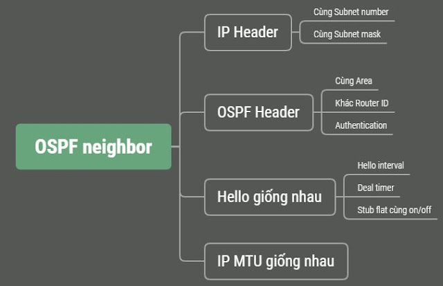
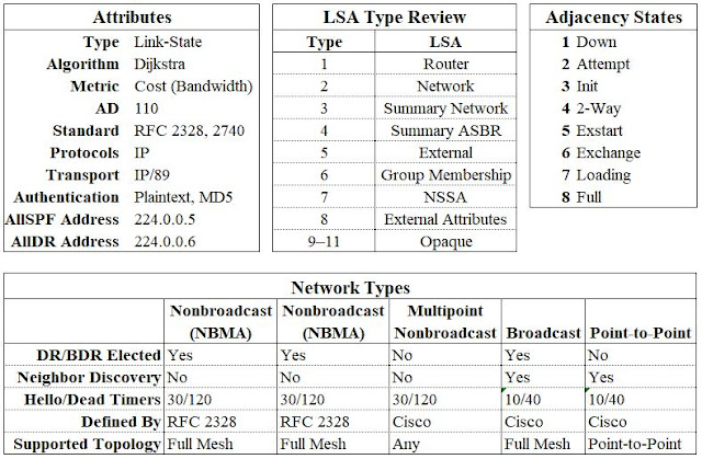
Giới thiệu: Để chuẩn bị cho phần trouble shooting trong OSPF mình tổng hợp lại các key (tham khảo OSPF SUMMARY ở đây) và các lệnh thường dùng để tiện cho việc xác định lỗi khi chạy giao thức OSPF trong hệ thống. 

1. Các điều kiện cơ bản để thiết lập neighbor


2. Các thuộc tính, LSA type, trạng thái


3. Ngoài ra còn có các nguyên nhân khác như: passive interface, access list, priority, .... cũng sẽ ảnh hưởng đến việc thiết lập neighbor trong OSPF. Chúng ta sẽ tìm hiểu rỏ hơn phần lab, nội dung bài lab sẽ giải quyết các vấn đề là:

  •  Không hiển thị danh sách router láng giềng
  •  Có trong danh sách láng giềng nhưng trạng không phải là FULL


4. Các common/câu lệnh thường sử dụng
Cơ bản
show ip [route | protocols]
show ip route summary
show ip ospf
show ip ospf interface
show ip ospf interface brief
show ip ospf database
show ip ospf database database-summary
show ip ospf neighbor
show ip ospf neighbor detail
show ip ospf neighbor <interface> detail
show ip ospf virtual-links
show ip ospf stat detail
show interface <interface>
show ip ospf interface <interface>

Debug
debug ospf [...]
debug ip ospf adjacency
debug ip ospf hello
debug ip ospf monitor

Type 3
show ip ospf database network <link state ID>
show ip ospf database summary <link state ID>

Type 4
show ip ospf database asbr-summary <link state ID>
show ip ospf border-routers

Type 5
show ip ospf database external <link state ID>

Type 7
show ip ospf database nssa-external <link state ID>

Xong!

Troubleshooting OSPF and Key

Giới thiệu: Để chuẩn bị cho phần trouble shooting trong OSPF mình tổng hợp lại các key (tham khảo OSPF SUMMARY ở đây) và các lệnh thường dùng để tiện cho việc xác định lỗi khi chạy giao thức OSPF trong hệ thống. 

1. Các điều kiện cơ bản để thiết lập neighbor


2. Các thuộc tính, LSA type, trạng thái


3. Ngoài ra còn có các nguyên nhân khác như: passive interface, access list, priority, .... cũng sẽ ảnh hưởng đến việc thiết lập neighbor trong OSPF. Chúng ta sẽ tìm hiểu rỏ hơn phần lab, nội dung bài lab sẽ giải quyết các vấn đề là:

  •  Không hiển thị danh sách router láng giềng
  •  Có trong danh sách láng giềng nhưng trạng không phải là FULL


4. Các common/câu lệnh thường sử dụng
Cơ bản
show ip [route | protocols]
show ip route summary
show ip ospf
show ip ospf interface
show ip ospf interface brief
show ip ospf database
show ip ospf database database-summary
show ip ospf neighbor
show ip ospf neighbor detail
show ip ospf neighbor <interface> detail
show ip ospf virtual-links
show ip ospf stat detail
show interface <interface>
show ip ospf interface <interface>

Debug
debug ospf [...]
debug ip ospf adjacency
debug ip ospf hello
debug ip ospf monitor

Type 3
show ip ospf database network <link state ID>
show ip ospf database summary <link state ID>

Type 4
show ip ospf database asbr-summary <link state ID>
show ip ospf border-routers

Type 5
show ip ospf database external <link state ID>

Type 7
show ip ospf database nssa-external <link state ID>

Cài đặt NIC Teaming trên Windows Server 2012*/2016*/2019*


Nhằm mục đích tăng băng thông và tính dự phòng cho card mạng server chúng ta có thể gộp/bó các card mạng lại với nhau thành 1 card mạng logic. Với cisco ta có kỹ thuật EtherChannel, trên windows chúng ta có thể dùng feature NIC Teaming để gộp nhiều card mạng thành 1 card mạng logic. Chúng ta có thể thực hiện trên các phiên bản Windows Server 2012*/2016*/2019*

Thực hiện:


5: là chọn card LAN 1 và LAN 2 thành một card mạng logic có tên 4: Team LAN1-LAN2

Kết quả:


Ta thấy Card mạng có tên Team LAN1-LAN2 đã được ra và băng thông đã được tăng lên (băng thông card này bằng tổng băng thông của các card khi được team vào). Đến đây chúng ta có thể đặt IP Address cho server trên card logic nàykhông đặt trên card LAN 1 hay LAN2.

Modify:

Chúng ta có thể điều chỉnh mode cho phù hợp với hệ thống hiện tại:
  • Nếu chọn mặt định thì trên switch chúng ta không cần phải cấu hình gì cả,
  • Nếu chọn mode là LACP thì trên switch phải cấu hình mode LACP (tham khảo cấu hình LACP trên switch cisco ở đây)


Chúng ta cũng có thể điều chỉnh thông tin VLAN nếu cần thiết. Thông thường để mặt định, cấu hình vlan thường thường là cấu hình trên switch đối với các port gắng vào thiết bị đầu cuối.

Xong!


/*header slide*/